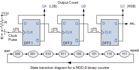
Mod 4 counter circuit diagram Copy of mod 8 synchronous counter using jk flip-flop Mod counters are truncated modulus counters
[Solved] Draw the circuit diagram of a MOD-32 synchronous counter using
Circuit diagram of mod 6 counter Circuit diagram for up down counter 8-bit binary counter circuit diagram
Bcd counter circuit using the 74ls90 decade counter
Design modMod 4 counter circuit diagram Counter mod diagram state counters modulus electronics truncatedSynchronous flop geeksforgeeks.
Mod 5 asynchronous counter circuit diagramMod 8 counter circuit diagram Counters modulus truncatedMod 6 counter circuit diagram.

Mod 8 counter circuit diagram
Mod 8 counter circuit diagramCircuit design of a 4-bit binary counter using d flip-flops – vlsifacts Counter bit flip using binary flops circuit output q3 q1 q2 q0 collected would finalMod counters are truncated modulus counters.
Design mod 5 asynchronous counter using jk flip flopMod 6 counter circuit diagram Counter mod modulus counters truncated electronics decadeMod 10 counter circuit diagram.

Counter mod circuit counters bcd tutorials flip using frequency divide flops count decade division modulus electronics toggle 74ls90 segment value
Mod 4 counter circuit diagramDesign mod-10 synchronous counter using jk flip flops.check for the Mod 8 counter circuit diagramDiagram mod counter ic circuit precautions block.
Mod counters are truncated modulus countersMod 6 counter circuit diagram Modulo 6 counter jk flip flopsCircuit diagram of mod 6 counter.

7490 decade counter pin configuration » hackatronic
Mod 5 asynchronous counter circuit diagramMod 6 counter circuit diagram Circuit diagram of mod 6 counterMod 6 counter circuit diagram.
Mod 6 counter circuit diagram[solved] draw the circuit diagram of a mod-32 synchronous counter using Contadores en lógica digital – acervo lima.


MOD Counters are Truncated Modulus Counters

Design Mod - N synchronous Counter - GeeksforGeeks

Mod 8 Counter Circuit Diagram

Mod 6 Counter Circuit Diagram

Mod 5 Asynchronous Counter Circuit Diagram - Wiring Diagram Line

Mod 5 Asynchronous Counter Circuit Diagram - IOT Wiring Diagram
[Solved] Draw the circuit diagram of a MOD-32 synchronous counter using

MOD Counters are Truncated Modulus Counters